brady bmp21 plus manual
Brady BMP21 Plus Manual: A Comprehensive Guide
Brady’s comprehensive guide unlocks the full potential of your BMP21 Plus‚ detailing features and functions for efficient label creation and reliable performance.
The Brady BMP21 Plus is a versatile‚ entry-level industrial label printer designed for a wide range of applications. It’s ideal for creating durable labels for general identification‚ component marking‚ and safety labeling needs. This printer empowers users to produce professional-quality labels quickly and easily‚ directly from its built-in software.
Whether you require labels for electrical panels‚ cable wraps‚ or asset tracking‚ the BMP21 Plus delivers reliable performance. It offers the flexibility of battery or AC adapter power‚ making it suitable for both on-site and in-office use. Registering your printer online at bradyid.com unlocks access to support and resources. This manual will guide you through setup‚ operation‚ and maintenance‚ ensuring you maximize the value of your new Brady BMP21 Plus.
What’s Included in the BMP21 Plus Kit?
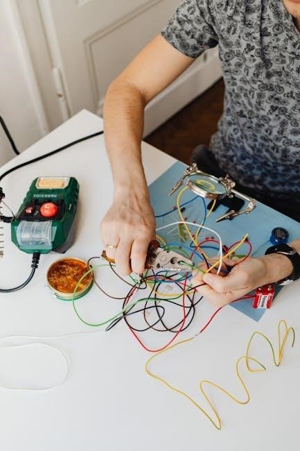
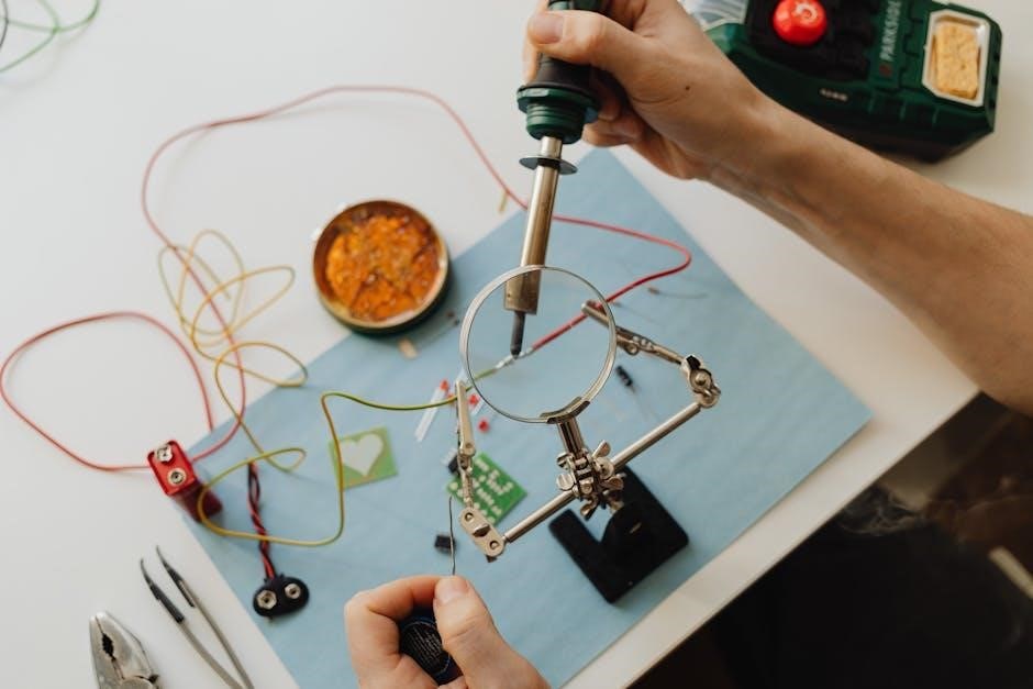
The Brady BMP21 Plus Printer Kit (195) provides everything needed to begin creating professional-grade labels immediately. Typically‚ the kit includes the BMP21 Plus printer itself‚ a starter roll of black on white label tape‚ and a USB port for connectivity.
You’ll also find a comprehensive quick start guide to assist with initial setup and operation. An AC power adapter is often included‚ offering an alternative to battery power. Importantly‚ the kit does not automatically include batteries; these must be purchased separately if you intend to use the printer without the AC adapter. Registration online at bradyid.com provides access to detailed manuals and further support resources to fully utilize your new printer.
Safety Precautions
Prioritize safety when operating the Brady BMP21 Plus. This device is intended for indoor use only‚ and precautions should be taken to avoid exposure to moisture or extreme temperatures. Always disconnect the power source – either remove batteries or unplug the AC adapter – before performing any maintenance or cleaning procedures.
Never attempt to disassemble or modify the printer beyond the instructions provided in this manual. Improper handling could result in electric shock or damage to the device. Ensure adequate ventilation during operation to prevent overheating. The included documentation‚ particularly the “Valore di sblocco questa guida‚” emphasizes understanding all features before use‚ ensuring safe and effective operation.

Getting Started with Your BMP21 Plus
Begin by choosing between battery or optional AC power‚ then register your printer online at www.bradyid.com for full access to resources.

Powering the Device: Batteries vs. AC Adapter
The Brady BMP21 Plus offers flexible power options to suit your labeling needs. You can operate the printer using standard batteries‚ providing portability for on-site labeling tasks where access to a power outlet is limited. This makes it ideal for field work‚ maintenance‚ and quick identification projects.
Alternatively‚ for extended use or stationary applications‚ an optional AC power adapter is available. Utilizing the AC adapter ensures a consistent power supply‚ eliminating the need for frequent battery changes and potentially saving costs over time. The adapter is particularly useful for high-volume labeling or when the printer is used continuously for prolonged periods. Consider your typical usage scenario to determine the most convenient and cost-effective power solution for your BMP21 Plus.
Registering Your Printer Online
To fully utilize your new Brady BMP21 Plus and access valuable resources‚ online registration is highly recommended. Visit www.bradyid.com to register your printer quickly and easily. Registration unlocks access to the latest software updates‚ ensuring optimal performance and compatibility.
Furthermore‚ registered users benefit from exclusive access to detailed support documentation‚ troubleshooting guides‚ and helpful tutorials. This allows you to maximize the printer’s capabilities and resolve any potential issues efficiently. Registration also enables Brady to provide you with important product announcements and information about new label materials and features. Don’t delay – register your BMP21 Plus today for a seamless labeling experience!
Initial Setup and Printer Configuration
Begin by carefully unpacking your BMP21 Plus kit and verifying all components are present. Before first use‚ install either batteries or connect the optional AC power adapter for a consistent power supply. Power on the device and follow the on-screen prompts to select your preferred language and date/time settings.
The printer will then guide you through a brief configuration process‚ including setting the label length and quality. Ensure the label tape is correctly loaded (detailed in a later section). A test print is recommended to confirm proper functionality and alignment. Familiarize yourself with the keypad and display for efficient navigation. Proper initial setup ensures optimal print quality and a smooth user experience.

Understanding the BMP21 Plus Interface
Mastering the keypad‚ display‚ and menu system is crucial for efficient label design and printing with your Brady BMP21 Plus printer.
Keypad and Display Overview
The Brady BMP21 Plus features an intuitive interface designed for ease of use. The keypad consists of tactile buttons for navigating menus‚ entering text‚ and controlling printer functions. Key buttons include power‚ shift‚ space‚ backspace‚ and dedicated keys for specific actions like print and select.
The display‚ typically a backlit LCD‚ provides clear visibility of your label design‚ menu options‚ and printer status. It shows characters‚ symbols‚ and formatting options as you create your labels. Status indicators on the display alert you to issues like low battery or label jams. Understanding the layout of both the keypad and display is fundamental to operating the BMP21 Plus effectively‚ allowing for quick and accurate label creation.
Navigating the Menu System
The BMP21 Plus utilizes a hierarchical menu system accessed via the keypad. Pressing the ‘Menu’ button reveals the main menu‚ offering options like ‘Edit Label’‚ ‘Print Setup’‚ ‘Printer Settings’‚ and ‘Help’. Use the up and down arrow keys to scroll through menu items‚ and the ‘Select’ button to enter a chosen menu.
Within each menu‚ further options are presented. The ‘Shift’ key often unlocks additional functions or character sets. To return to the previous menu‚ press the ‘Back’ or ‘Escape’ key. Familiarizing yourself with this structure is crucial for customizing label designs‚ adjusting printer settings‚ and accessing helpful information. Remember to save your work frequently to avoid losing progress!
Understanding Status Indicators
The BMP21 Plus features several status indicators on its display to communicate printer status. A solid ‘Power’ light confirms the device is on‚ while a flashing light may indicate a low battery. The ‘Data’ light blinks during data transfer and is solid when ready to print. A ‘Tape’ indicator signals tape presence and movement; a flashing signal suggests a tape issue.
Error messages are displayed as codes on the screen‚ referencing the manual for specific troubleshooting steps. Pay attention to these indicators – they provide vital clues about the printer’s operation. Ignoring them could lead to print quality issues or even printer malfunction. Regularly checking these indicators ensures smooth and efficient label printing.

Creating and Printing Labels
Begin by loading compatible label tape‚ then utilize the built-in software to design labels with customized text‚ fonts‚ and symbols for optimal results.
Loading Label Tape
Proper label tape loading is crucial for optimal printing performance with your Brady BMP21 Plus. First‚ ensure the printer is powered off. Open the label compartment‚ typically located on the side or top of the device. Insert the label roll onto the spindle‚ ensuring it unwinds correctly – usually counter-clockwise.
Thread the label tape through the printer’s internal path‚ following the guides indicated within the compartment. These guides ensure the tape travels smoothly during printing. Finally‚ close the label compartment securely. The BMP21 Plus automatically detects the tape type‚ but verifying this setting within the printer’s menu is recommended. Incorrect loading can lead to jams or poor print quality‚ so double-check each step for a seamless experience.
Designing Labels with the Built-in Software
The Brady BMP21 Plus features intuitive built-in software for creating customized labels directly on the device. Access the label design mode through the printer’s menu system. Utilize the keypad to input text‚ selecting from various fonts‚ sizes‚ and styles to achieve your desired appearance.
The software allows for straightforward text editing‚ including alignment and justification. Explore options to add pre-defined symbols or create simple graphics. Preview your label design before printing to ensure accuracy. Save frequently used designs for quick recall‚ streamlining future labeling tasks. This integrated software provides a user-friendly experience‚ eliminating the need for external computer connectivity for basic label creation.
Selecting Fonts‚ Sizes‚ and Styles
The BMP21 Plus offers a range of font options to suit diverse labeling needs. Navigate the menu to access font selection‚ choosing from standard fonts like Arial and Courier‚ or specialized options for specific applications. Adjust font size to ensure readability‚ with options ranging from small to large characters.
Experiment with different styles – bold‚ italic‚ and underline – to emphasize key information. The printer supports various text formatting features‚ allowing you to create visually appealing and informative labels. Preview your selections on the display to confirm the desired look before printing. Consider the label’s intended use when choosing fonts‚ sizes‚ and styles for optimal clarity and impact.
Adding Symbols and Logos
Enhance your labels with a library of pre-installed symbols‚ offering quick access to common warnings‚ hazard signs‚ and directional indicators. The BMP21 Plus allows importing custom logos and graphics to personalize your labels and reinforce branding. Ensure imported images are compatible with the printer’s resolution for optimal print quality.
Utilize the built-in software to position and resize symbols and logos precisely on your label design. Consider the overall label layout and ensure symbols complement the text without cluttering the design. Properly sized symbols improve clarity and convey information effectively. Explore the symbol library and import options to create professional-looking‚ informative labels.

Advanced Features and Functions
Unlock powerful capabilities like barcode and QR code printing‚ multiple copies‚ and design saving for streamlined workflows and enhanced label management efficiency.
Using Barcodes and QR Codes
The Brady BMP21 Plus empowers users to integrate barcodes and QR codes directly into their label designs‚ enhancing tracking and data management capabilities. This feature is invaluable for asset tracking‚ inventory control‚ and various industrial applications requiring scannable identification. The built-in software allows for easy selection of common barcode symbologies‚ ensuring compatibility with standard scanning equipment.
Users can input data manually or import it from external sources to generate unique barcodes or QR codes for each label. Proper configuration of barcode settings‚ such as width and height‚ is crucial for optimal readability. QR codes offer the advantage of storing larger amounts of information‚ making them ideal for applications needing detailed product information or web links. Ensure the printed barcodes and QR codes are clear and free from defects for reliable scanning performance.
Printing Multiple Copies
The Brady BMP21 Plus simplifies the process of producing multiple identical labels‚ saving time and ensuring consistency across applications. Within the printer’s interface‚ users can easily specify the desired number of copies to print for each label design. This functionality is particularly useful for labeling large volumes of items‚ such as asset tags‚ component identifiers‚ or warehouse inventory.
To initiate multiple copy printing‚ simply enter the quantity needed before starting the print job. The printer will automatically produce the specified number of labels in sequence. Regularly checking the label supply is recommended during longer print runs to avoid interruptions. This feature streamlines workflows and minimizes manual repetition‚ boosting overall productivity and efficiency in labeling tasks.
Saving and Recalling Label Designs
The Brady BMP21 Plus offers a convenient memory function‚ allowing users to save frequently used label designs for quick and easy recall. This eliminates the need to recreate labels from scratch each time‚ significantly improving workflow efficiency. Saved designs can be stored directly within the printer’s internal memory‚ providing access to customized templates whenever needed.
To save a design‚ navigate to the save option within the printer’s software interface and assign a unique name or identifier. Recalling a saved design is equally straightforward – simply select it from the memory list. This feature is invaluable for maintaining consistency in labeling practices and streamlining repetitive tasks‚ ensuring professional and accurate results every time.

Troubleshooting Common Issues
Resolve typical problems like power failures‚ label jams‚ and connectivity issues with this section’s guidance‚ ensuring your Brady BMP21 Plus operates smoothly and reliably.
Printer Not Powering On
If your Brady BMP21 Plus fails to power on‚ begin by verifying the battery installation. Ensure batteries are correctly inserted with proper polarity‚ or try a fresh set. Alternatively‚ confirm the AC adapter is securely connected to both the printer and a functioning power outlet.
Check the power cable for any visible damage. If using batteries‚ a low battery indicator might appear – replace them immediately. If utilizing the AC adapter‚ test the outlet with another device to rule out power source issues. A faulty adapter could also be the culprit; consider testing with a known working adapter if available.
Finally‚ inspect the printer’s power button for any physical obstructions or damage. A stuck or broken button could prevent activation. If none of these steps resolve the issue‚ further technical support may be required.
Label Jams and Errors
Experiencing label jams or errors with your Brady BMP21 Plus? First‚ power off the printer and carefully open the label compartment. Gently remove any jammed label material‚ avoiding tearing. Inspect the label path for any obstructions like small debris or adhesive residue. Ensure the label tape is loaded correctly‚ following the diagram within the printer.
Error messages on the display provide clues. Consult the manual for specific error code definitions. Incorrect label type selection can also cause jams; verify you’ve chosen the correct material setting. Avoid using damaged or low-quality label tape‚ as this increases jam risk.
If jams persist‚ clean the printhead and platen roller with a lint-free cloth. A dirty printhead can contribute to feeding issues.
Connectivity Problems
If you’re encountering connectivity issues with your Brady BMP21 Plus‚ begin by verifying the physical connection if using an optional AC adapter. Ensure the power cord is securely plugged into both the printer and a functioning outlet. For USB connectivity‚ confirm the cable is properly connected to both the printer and your computer.
Check your computer’s device manager to see if the BMP21 Plus is recognized. If not‚ you may need to reinstall the printer drivers‚ available for download on the Brady website (www.bradyid.com). Ensure your computer meets the minimum system requirements.
Restart both the printer and your computer. Sometimes a simple reboot resolves communication glitches. Verify no other devices are interfering with the USB port.

Maintenance and Care
Regular cleaning‚ printhead replacement‚ and proper storage are crucial for maintaining optimal performance and extending the lifespan of your Brady BMP21 Plus printer.
Cleaning the Printer
To ensure consistent print quality and prevent potential issues‚ regularly clean your Brady BMP21 Plus. Begin by disconnecting the power source – either removing batteries or unplugging the AC adapter. Use a soft‚ lint-free cloth lightly dampened with isopropyl alcohol to gently wipe down the exterior surfaces of the printer. Avoid harsh chemicals or abrasive cleaners‚ as these can damage the plastic casing.
Pay particular attention to the label feed path and printhead area. Carefully remove any accumulated dust or debris using a dry cotton swab. For stubborn residue‚ slightly dampen the swab with isopropyl alcohol‚ ensuring it’s not dripping wet. Never directly apply liquid to the printer’s internal components. Allow all surfaces to completely dry before reconnecting the power and resuming operation. Consistent cleaning contributes significantly to the longevity and reliability of your BMP21 Plus.
Replacing the Printhead
Over time‚ the printhead of your Brady BMP21 Plus may wear down‚ resulting in faded or incomplete prints. Replacing it restores optimal label quality. First‚ ensure the printer is powered off and disconnected from any power source. Open the printer cover to access the printhead. Gently release the old printhead by following the release mechanism – typically a small lever or button.
Carefully insert the new printhead‚ ensuring it clicks securely into place. Avoid touching the printhead’s surface with your fingers‚ as oils can affect performance. Close the printer cover and power on the device. It’s recommended to print a test label to verify the new printhead is functioning correctly. Regular printhead replacement‚ based on usage‚ maintains consistent‚ high-quality label output.
Storing the BMP21 Plus
Proper storage extends the life of your Brady BMP21 Plus printer. When not in use for extended periods‚ always remove the batteries to prevent potential corrosion and damage. Store the printer in a clean‚ dry environment‚ away from direct sunlight‚ extreme temperatures‚ and dust. A protective carrying case is recommended for added security during transport or storage.
Avoid storing the printer with label tape loaded‚ as prolonged pressure can potentially affect the printhead. Ensure all components‚ including the AC adapter if applicable‚ are stored together for easy access. Regular cleaning before storage helps maintain optimal performance when you resume printing. Following these guidelines ensures your BMP21 Plus remains in excellent working condition.

Technical Specifications
The Brady BMP21 Plus offers detailed specifications regarding dimensions‚ weight‚ print resolution‚ speed‚ and compatibility with various label tape types.
BMP21 Plus Dimensions and Weight
Understanding the physical characteristics of the Brady BMP21 Plus is crucial for workspace planning and portability considerations. While precise measurements can vary slightly depending on accessories‚ the printer is generally designed to be compact and lightweight for convenient use in diverse environments.
Typically‚ the BMP21 Plus boasts dimensions that allow for easy integration into various labeling workflows‚ whether in a busy industrial setting or a mobile repair operation. Its relatively small footprint minimizes space requirements‚ while its manageable weight ensures comfortable handling during extended labeling tasks.
Specific dimensions and weight details are readily available in the official Brady documentation and product specifications‚ providing users with accurate information for logistical planning and transportation purposes. This ensures a seamless experience from setup to operation.
Print Resolution and Speed
The Brady BMP21 Plus delivers dependable print quality and efficiency for a wide range of labeling applications. Its print resolution is optimized to produce clear‚ legible text and graphics on various label materials‚ ensuring durability and readability in demanding environments.
Print speed is a key factor for productivity‚ and the BMP21 Plus is engineered to provide a balance between speed and quality. While exact speeds depend on label type‚ complexity of the design‚ and selected settings‚ it consistently delivers labels at a practical pace.
Users can expect crisp‚ professional-looking labels suitable for asset identification‚ safety warnings‚ and general-purpose labeling needs. Detailed specifications regarding dots per inch (DPI) and print speed are available in the official Brady product documentation.

Supported Label Tape Types
The Brady BMP21 Plus printer boasts impressive versatility‚ accommodating a broad spectrum of label tape types to suit diverse application requirements. It expertly handles durable labels designed for harsh industrial environments‚ alongside specialized materials for specific needs.
Supported materials include vinyl tapes known for their resistance to chemicals‚ abrasion‚ and temperature extremes‚ as well as polyester tapes offering exceptional durability and clarity. Furthermore‚ the printer works seamlessly with pre-printed labels and heat-shrink sleeves.
Brady offers a comprehensive range of compatible tapes‚ ensuring optimal performance and adhesion. Refer to the official Brady compatibility guide for a complete list of supported materials and dimensions‚ guaranteeing the perfect label for every task.